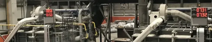
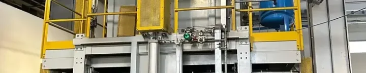
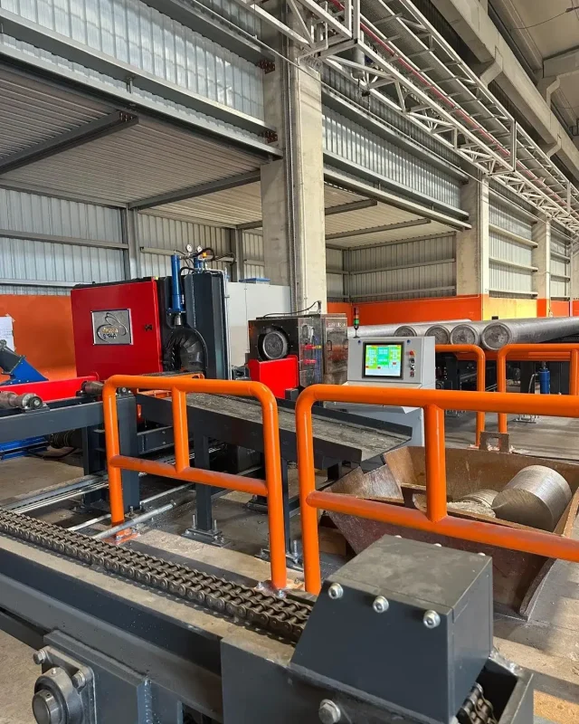
We combine the automatic saw and ultrasonic testing on a single line
We scan the internal structure of the billet automatically, immediately after cutting and without stopping the line. A part with a defect is marked and separated from the flow, and the test report is recorded together with the casting parameters. We build the system with reference to the EN 12258 and ASTM B594 standards and define the acceptance criteria according to your customer specification.
- Method
- Pulse-echo UT
- Diameter range
- 75 – 300 mm
- Position
- In-line, after cutting
- Output
- Defect map + report
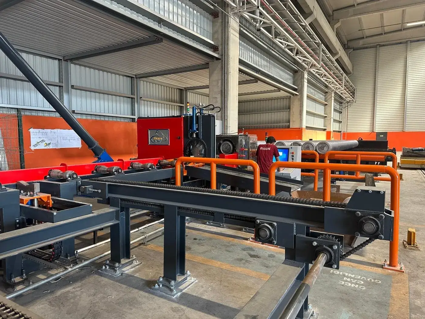
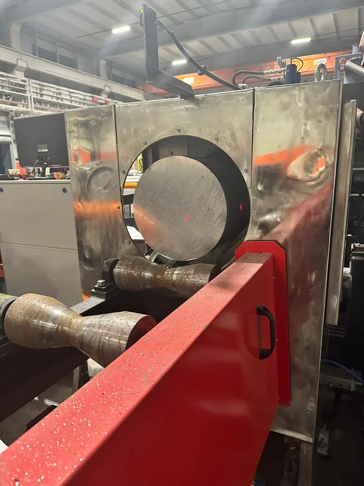
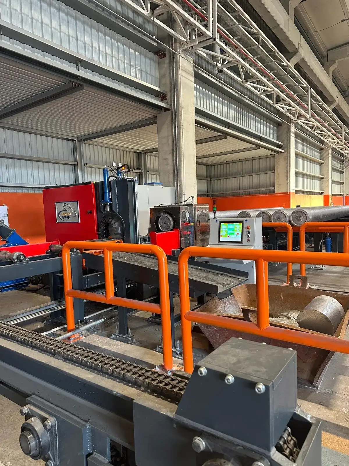
Ultrasonic testing system technical specifications
- Test method
- Pulse-echo ultrasonic, water-coupled scanning
- Scanning
- 360° across the billet cross-section
- Diameter range
- 75 – 300 mm
- Cutting unit
- Automatic saw; synchronised with line speed
- Transfer
- Automatic transfer from the cutting unit to the test station
- Decision
- Part is marked when the threshold value is exceeded — the line does not stop
- Reporting
- Defect map and test report (PDF) for each billet
- Correlation
- Matching with casting speed, temperature and water flow rate data
- Control
- PLC + SCADA; logging to the production database
- Status
- System patent-pending
- Retrofit
- Can be added later to existing casting lines
What is ultrasonic testing?
A high-frequency sound wave is passed through the metal. If there is a crack, void or density difference in its path, the wave is reflected from it; the returning echo is read by the sensor, and the location and size of the defect are derived from it. The method is non-destructive and involves no radiation. It is widely required for billet acceptance in aerospace, defence and automotive supply chains.
Testing runs from cutting to report in five steps
Casting and cutting
The casting machine produces billets of the specified diameter and length; the automatic saw integrated into the line does the cutting.
Automatic transfer
The cut billet is transferred to the test station along the line. No operator intervention.
Scanning
Water-coupled probes scan the billet cross-section through 360°; echo data is collected.
Evaluation
The software compares the echoes against threshold values. A part that exceeds the limit is marked, and the line flow does not stop.
Reporting
A defect map and a test report are generated for each billet, correlated with the casting parameters and archived.
We install the system on new lines and on lines already in operation
Automatic Saw + UT Station
For new casting lines. Cutting and scanning in a single unit, running in sync with line speed.
UT Station Only
For lines that already have a cutting unit. A test station is added to the transfer line.
Retrofit Package
Adaptation to casting lines not built by Gumen. The transfer distance and control interface are examined on site.
Weighing and Packing Module
Stacking, weighing and packing after testing; details are on the Automatic Loading and Unloading page.
Report Integration
Production database or ERP connection; details are on the PLC / SCADA Systems page.
Four things set this system apart
Testing happens inside the line
As soon as the billet is cut, it is scanned without the line stopping. Moving to a separate test station and waiting there are eliminated.
The defect is recorded together with its source
The scan data is matched with the casting speed, temperature and water flow rate. When a defect appears, you can see which parameter deviated.
The system produces the report
A defect map and a test report are produced automatically for every billet. No separate paperwork has to be prepared for customer audits or export.
Installs on existing lines too
On a line that has a cutting unit only the test station is added; on one that does not, it is added together with the saw. In both cases it communicates with the existing control system.
Explore the technical documents and catalogues
We answer frequently asked questions
about the ultrasonic testing system
No. Scanning is carried out while the billet is being transferred after cutting and is sized to the line speed. The line does not stop when a defective part is found either; only that part is marked and separated.
Internal cracks, gas voids and segregation zones that create density differences. The threshold values are set according to the standard you work to and the customer specification.
A patent application has been filed; this information will be updated when the registration process is complete. The distinctive aspect of the application is that ultrasonic scan data is recorded simultaneously with the casting machine’s parameters and correlated with them.
As a PDF test report and a defect map for each billet. If required, they can also be supplied in a form that can be transferred to the production database or ERP system.
Yes, if the transfer line has sufficient distance and a suitable control interface. After a site survey we state in writing what will be added and what will be adapted.
Which line is this system part of, and what runs before and after it?
Ultrasonic Test Systems
How does bringing testing into the line change production and documentation?
DISCOVER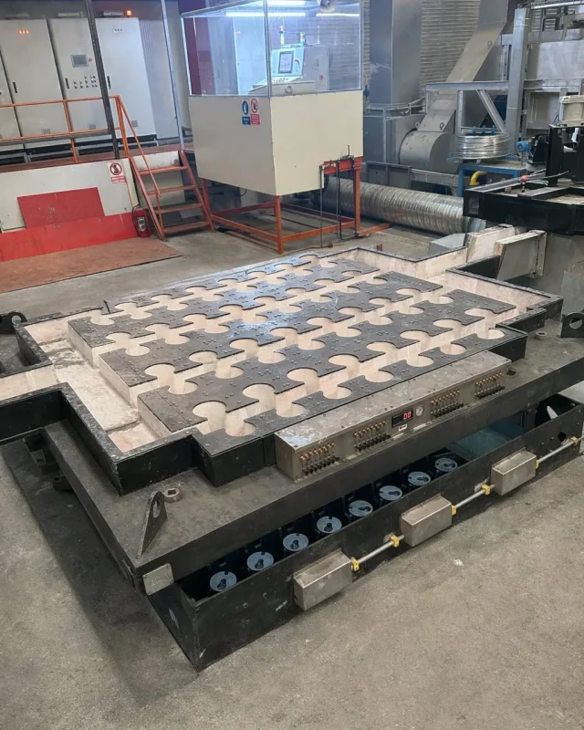
Vertical Casting Machine
Where the scanned billet comes from: the pit, mould table and water control.
DISCOVER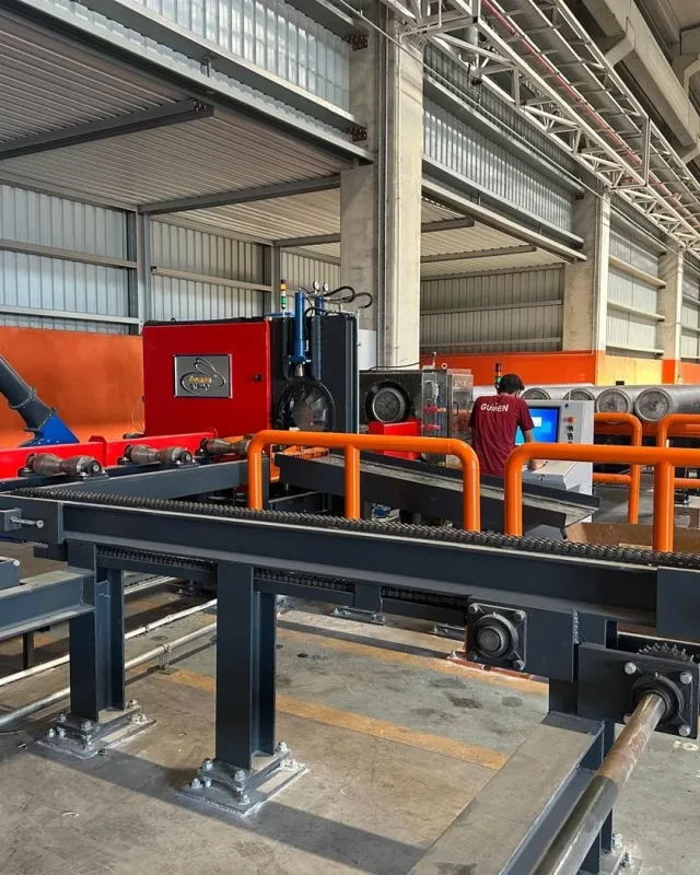
Automatic Billet Cutting
The saw that cuts the long billet to length, followed by weighing and stacking.
DISCOVER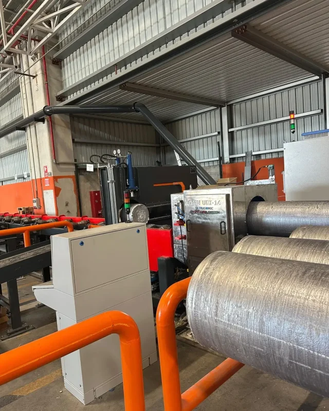
Automatic Loading & Unloading
The final stop for the billet after testing: stacking, weighing and packing.
DISCOVERLet us survey your casting line on site
What diameters of billet do you cast, how much distance is there in the post-cutting transfer, and which standard do you deliver to? After a site survey we state in writing what will be added.
Request a Quote