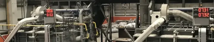

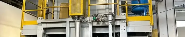
We build the melting and holding line as a single system
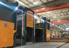
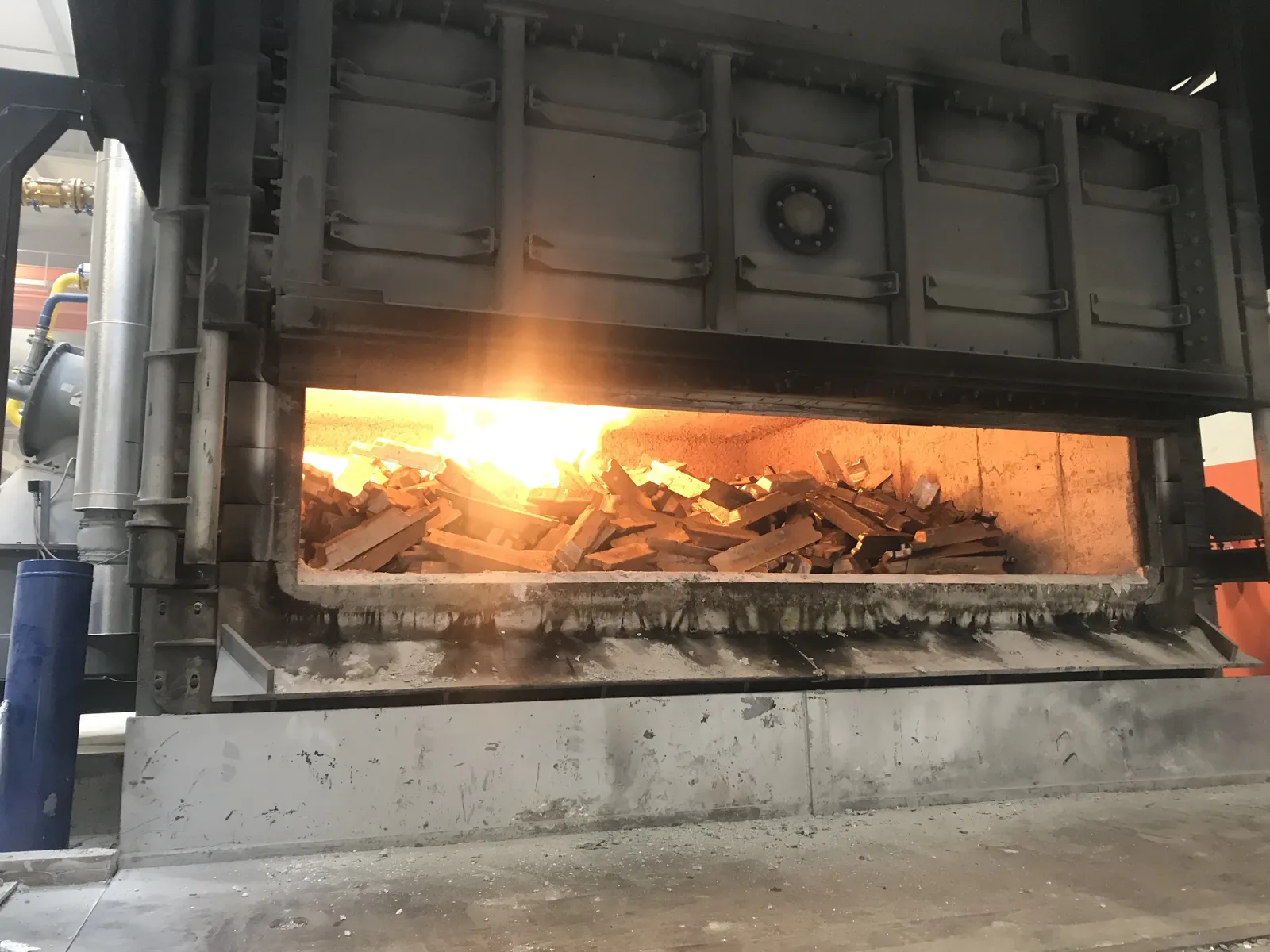
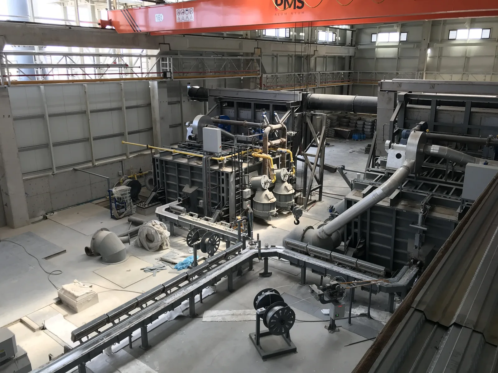
We bring the furnace, charging machine, combustion system and automation together in one project; every decision, from door size to bath depth, follows from your charge profile. In an aluminium plant, the largest items of fuel use and metal loss both arise in the furnace: we design the line to bring these two costs down.
- Capacity range
- 500 kg – 60 tonnes
- Operating temperature
- 700 – 850 °C
- Heating
- Gas / Electric
- Control
- PLC-based
Up to 25% savings in fuel consumption
The regenerative burner returns the heat of the flue gas to the combustion air, and an automatic damper that monitors furnace pressure cuts door and flue losses. The range measured on the burner side is 20–25%. The gain depends on how many hours a day the furnace runs and at what flue gas temperature; we make this calculation at the quotation stage, using the plant’s own shift schedule.
Why Gumen Makina Melting Systems?
Flexible capacity
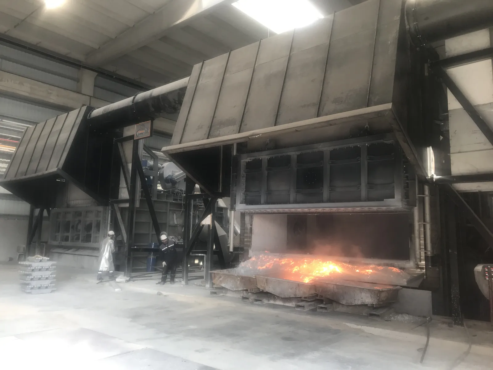
A 500 kg furnace and a 60-tonne furnace are not the same engineering, but they come from the same place. If your charge is mostly ingot, a single chamber is often enough; as the scrap share rises, the twin-chamber design pulls ahead.
Precise transfer
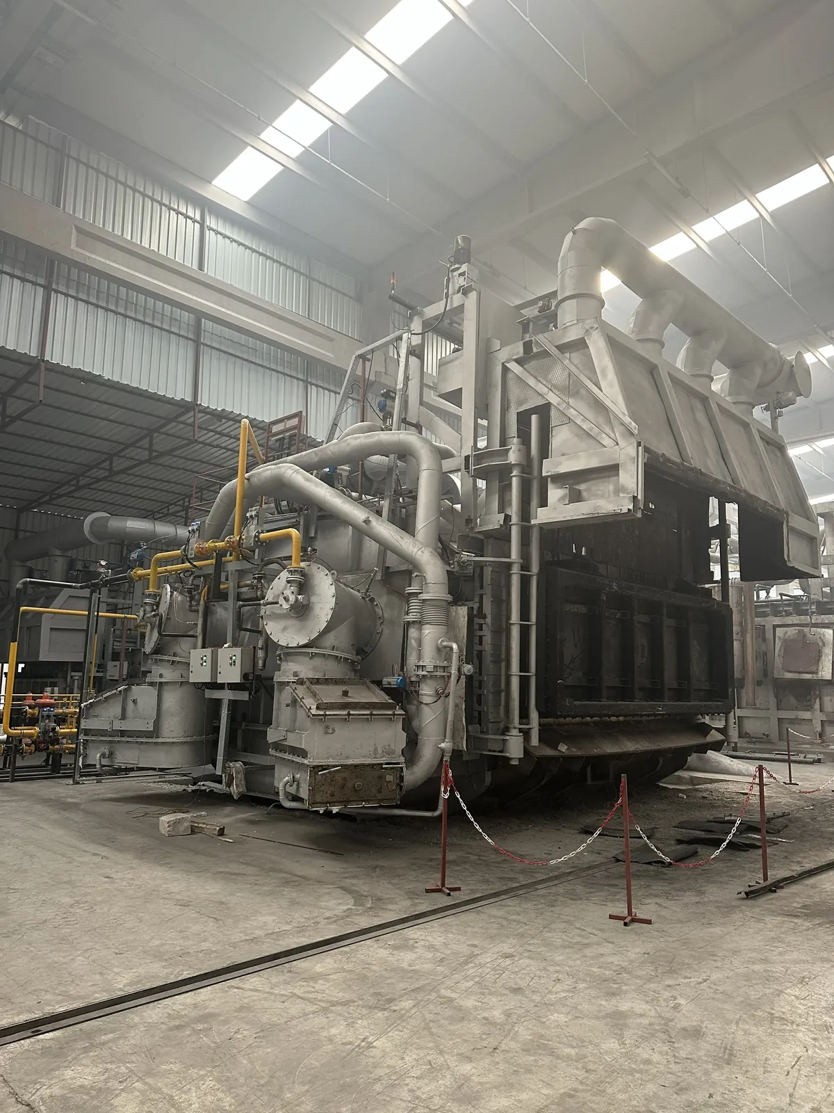
The tilting body discharges the metal under hydraulic control. A smooth flow reduces both dross carry-over into the ladle and air entrainment in the molten metal.
Heat recovery
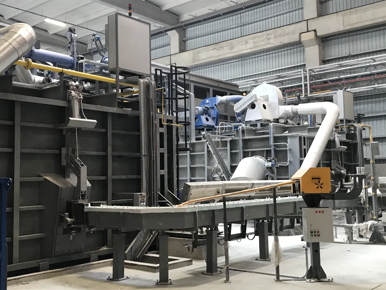
The regenerative burner gives the heat of the flue gas back to the combustion air. In this way, part of the energy that would leave through the stack returns to the furnace.
Smart pressure control
The damper monitors the internal pressure of the furnace and adjusts itself. This limits the heat escaping through the door and the flue, and the operator does not need to intervene constantly.
Three main units, in a single project
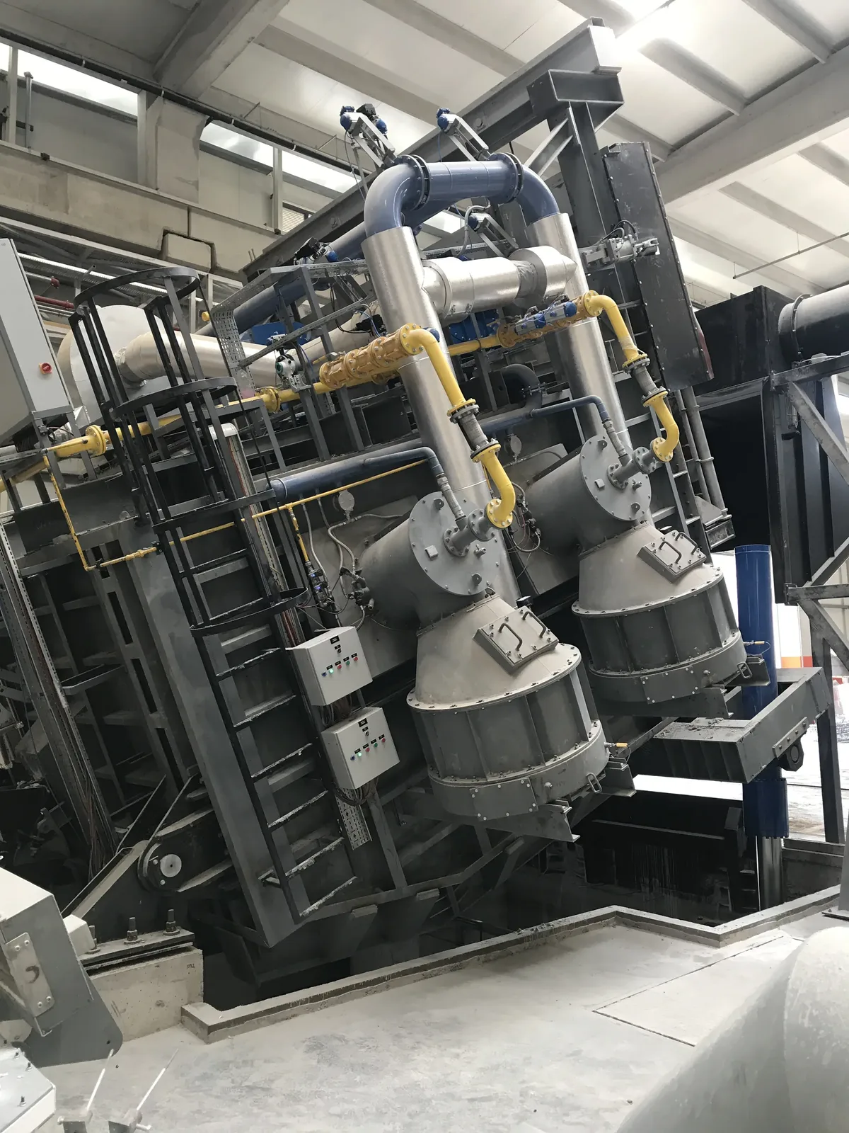
Twin-Chamber Furnaces
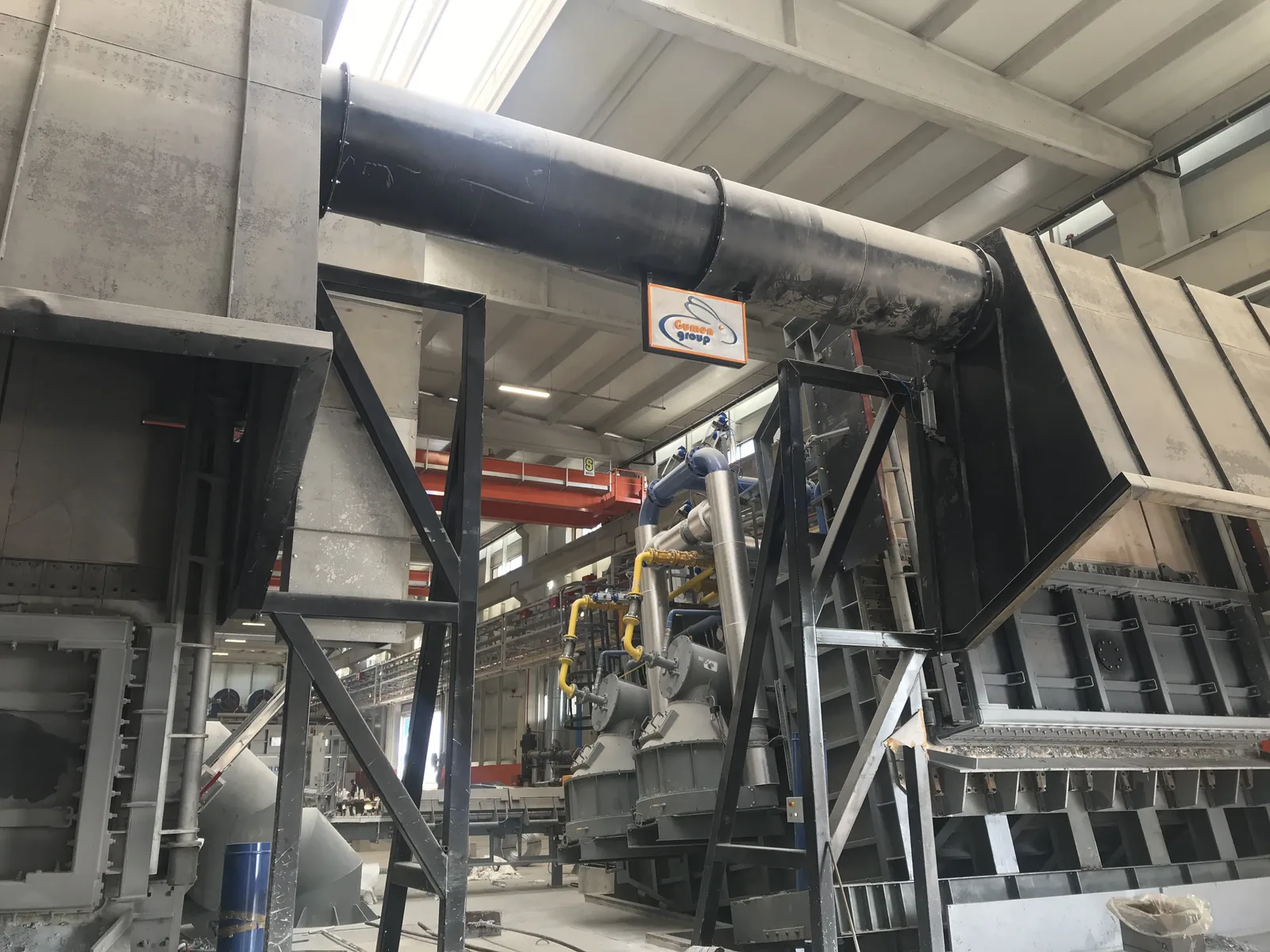
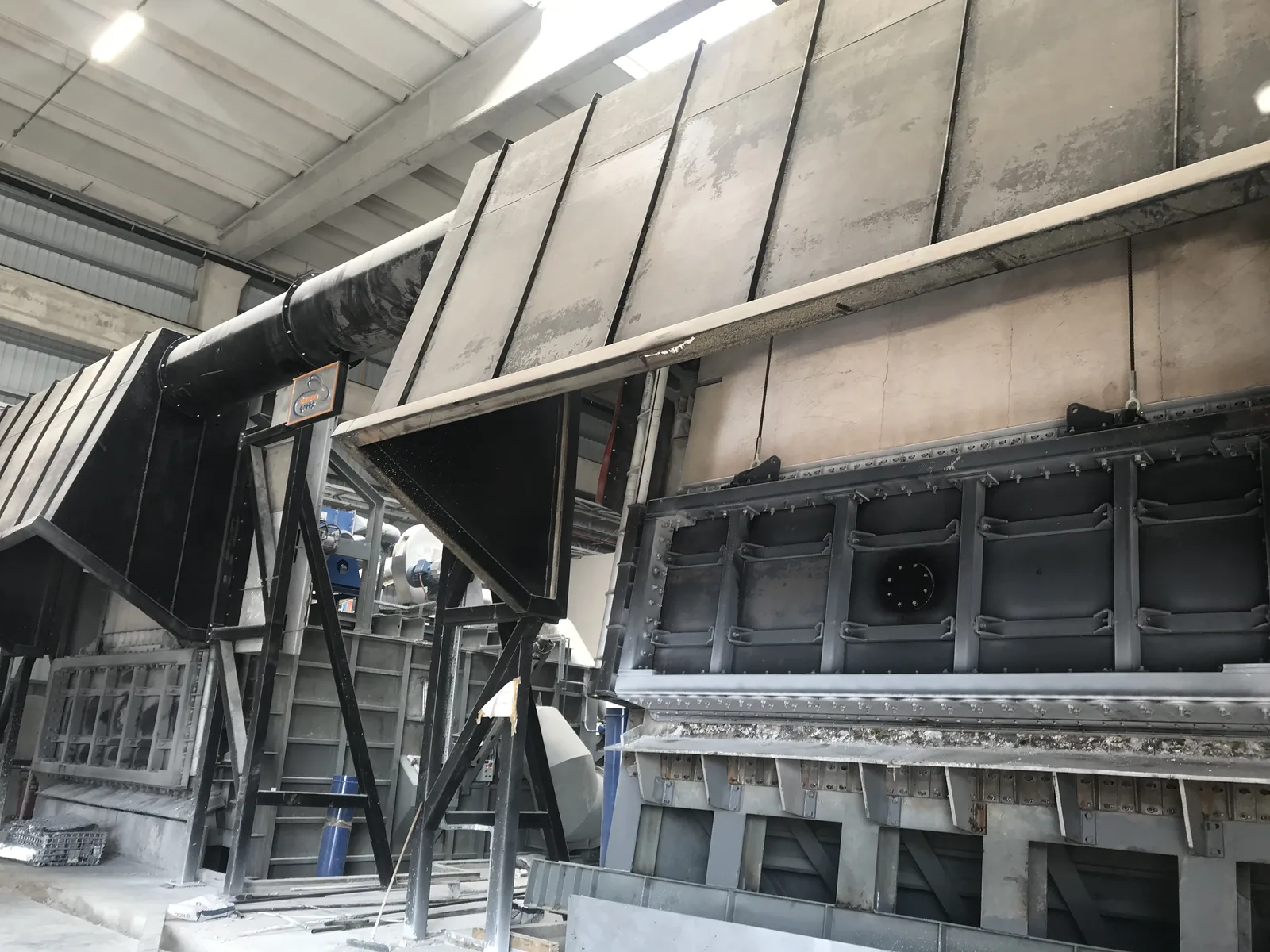
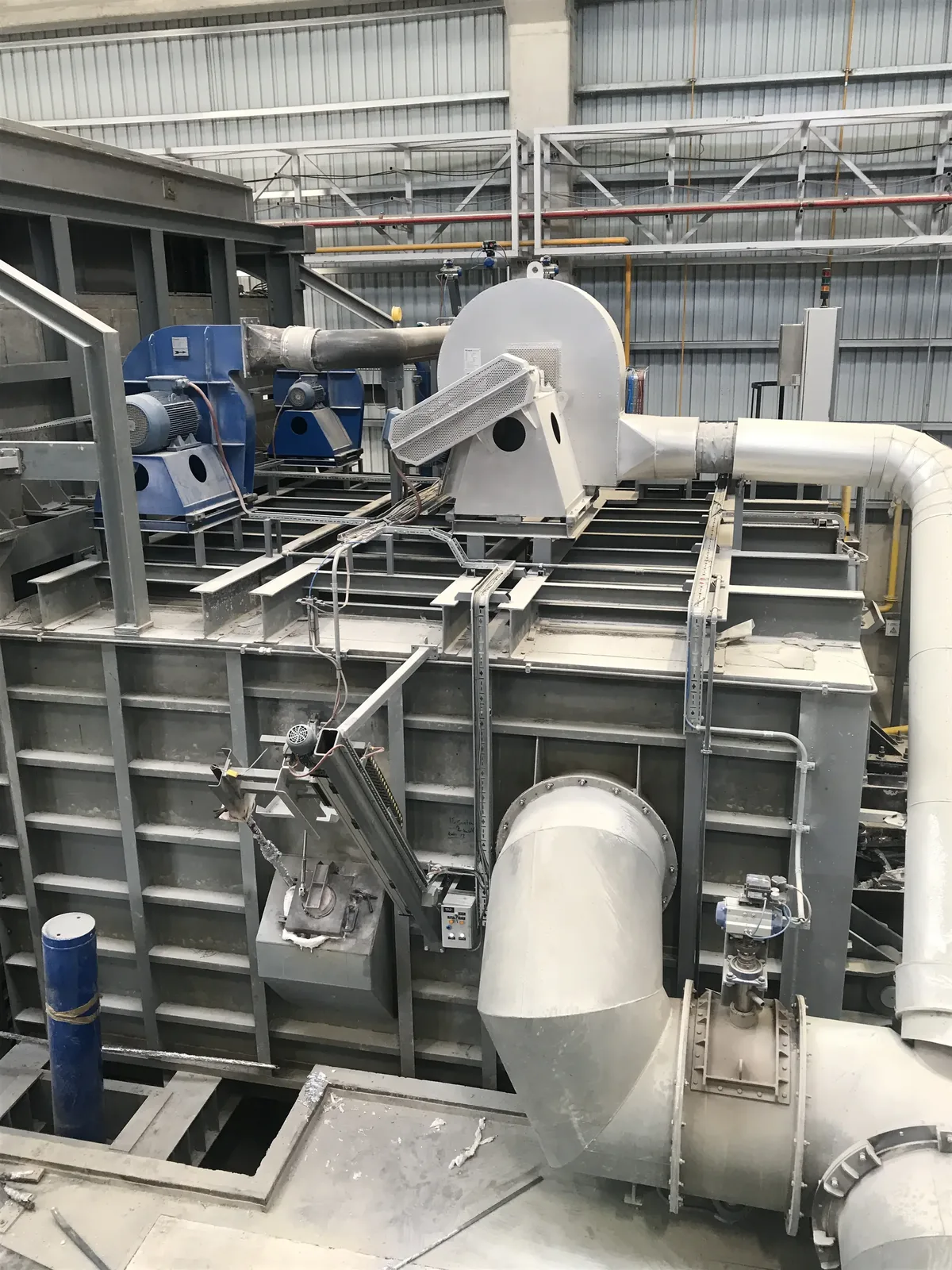
System structure: melting chamber, holding chamber, metal transfer channels between the chambers, combustion system and automation infrastructure. When melting and holding run in separate chambers, the two processes do not wait for each other: while the charge melts on one side, the other side holds metal ready for casting at temperature.
- Separate melting and holding chambers
- Independent process control for each chamber
- Smooth metal transfer between chambers
- Separate heat management for each chamber
- Stable metal quality and production continuity
- Integrated operation with continuous casting lines
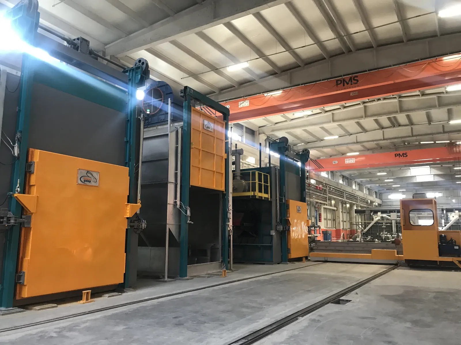
Charging and Feeding Systems
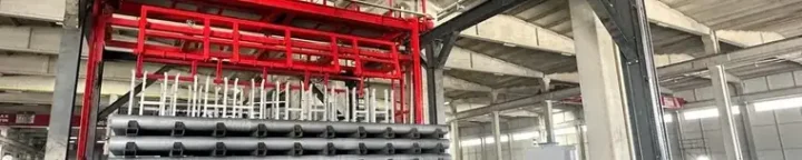
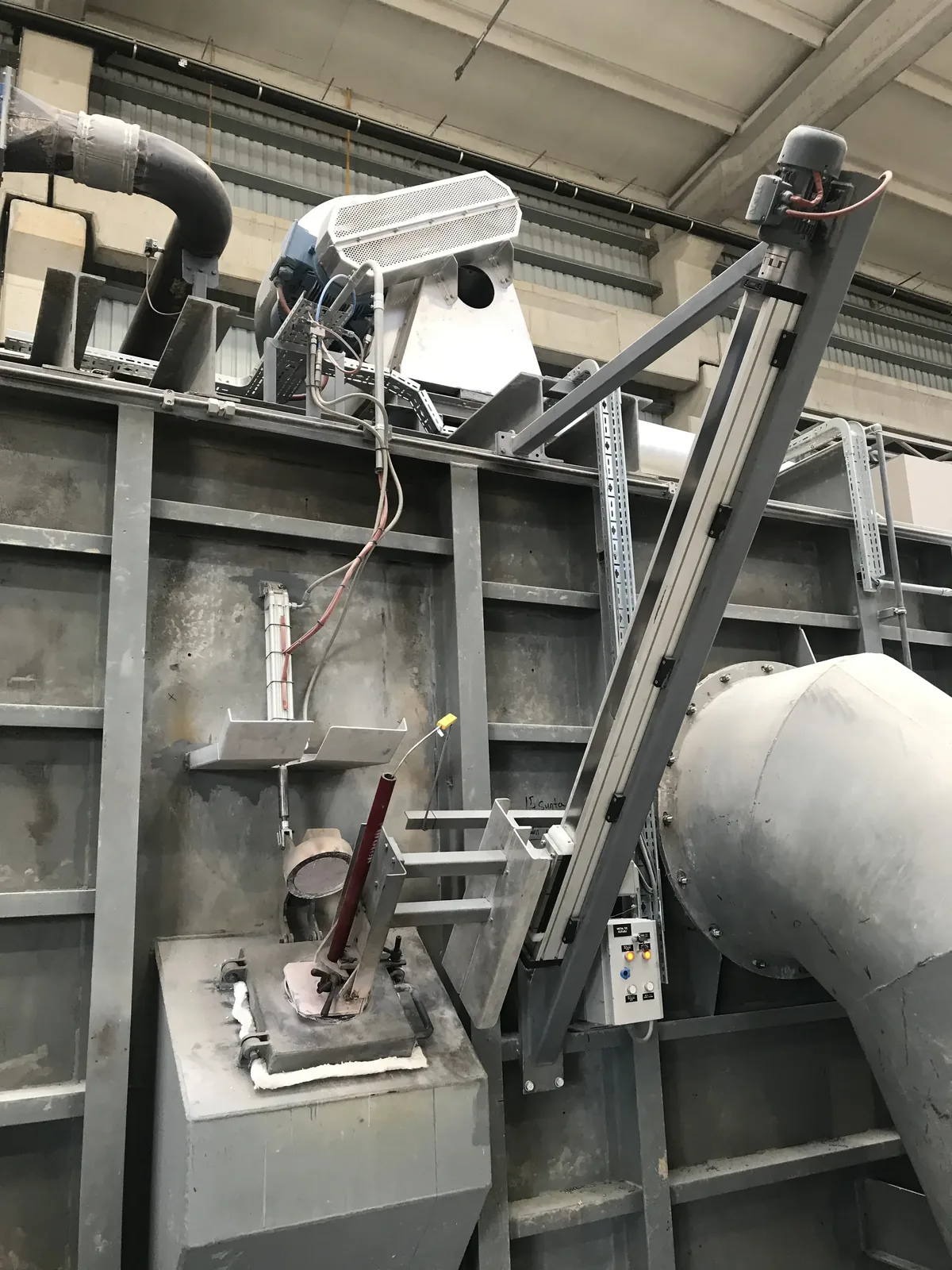
System structure: feeding unit, conveying mechanism, loading platform and automation control infrastructure. A door left open for a long time puts both the heat and the operator at risk; we build the cycle around this.
- Automatic and semi-automatic operation option
- Design flexible for different scrap sizes and types
- Feeding synchronised with furnace demand
- Cycle that shortens door-open time
- Loading designed for operator safety
- Labour efficiency and operational continuity
Combustion and Burner Systems
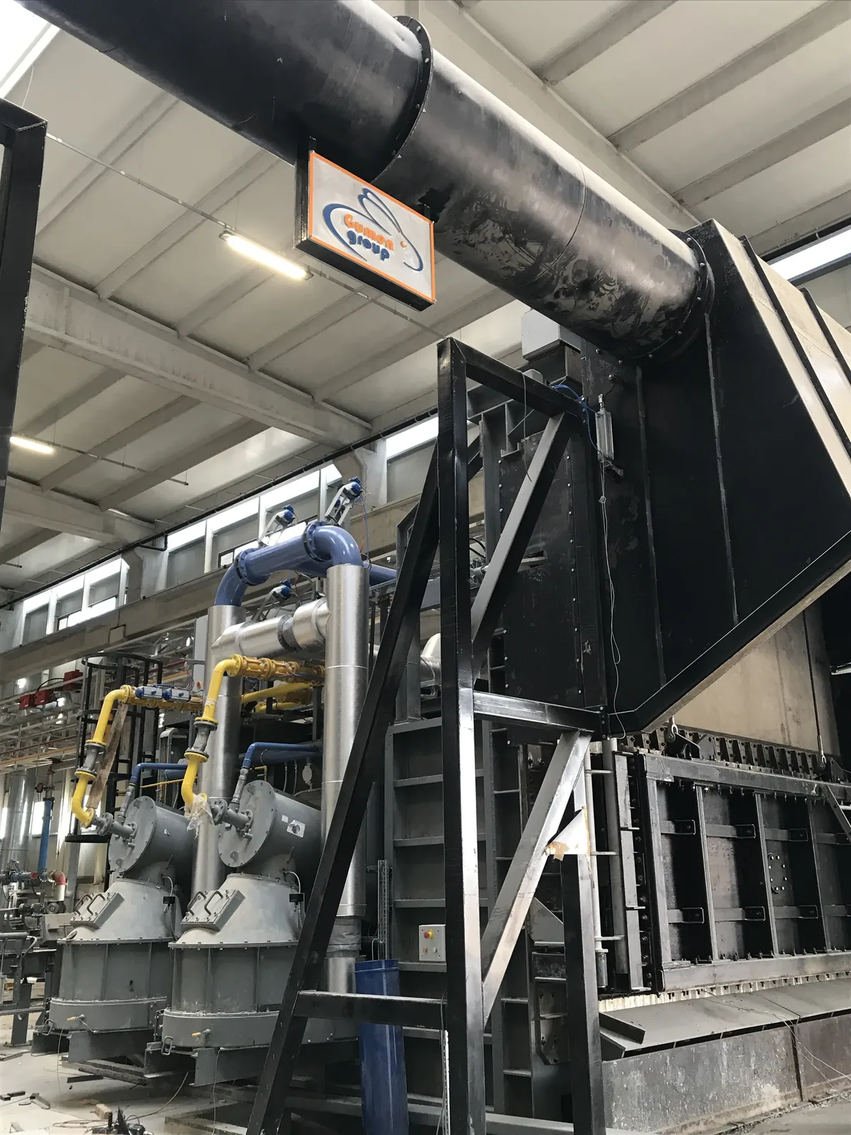
System structure: burner unit, air-gas mixing system, regenerative structure, flue line and automation control system. This is the section that determines the fuel bill; on existing furnaces it can often be refurbished without touching the furnace body.
- Regenerative heat recovery (20–25% savings)
- Automatic air-gas ratio control
- Damper operating on furnace pressure
- High and stable combustion efficiency
- PLC-integrated combustion management
- Combustion system refurbishment on existing furnaces
Technical documents and catalogues
We answer frequently asked questions
about the melting line
Not on nominal tonnage, but on the daily casting programme of the plant. Casting tonnage per shift, the ingot-to-scrap ratio in the charge and the duration of one cast determine the capacity. Choosing too large is also a problem: a furnace running half full burns more fuel per unit of metal.
If your charge is mostly ingot and casting is intermittent, a single chamber is often enough. As the scrap share rises, or when a continuous casting line has to be fed, the twin chamber comes to the fore: while the charge melts on one side, the other side holds the metal ready for casting.
We plan the scope around your production calendar; the burner, air-gas control and automation side can in most cases be renewed without touching the furnace body. The combustion system refurbishment on the sheet casting line at Panda Aluminium was carried out with this approach, keeping the existing equipment running.
In four areas: burner selection and regenerative/recuperative heat recovery, body insulation, charging automation that shortens door-open times, and combustion control that continuously adjusts the air-gas ratio. Which of them takes priority depends on how your furnace is operated.
Yes. Design, manufacturing, installation, first heat-up after refractory work and commissioning are carried out by the same team; operator training is given during commissioning. We also take on maintenance and service afterwards.
We manufacture the equipment that makes up this solution in our own plant
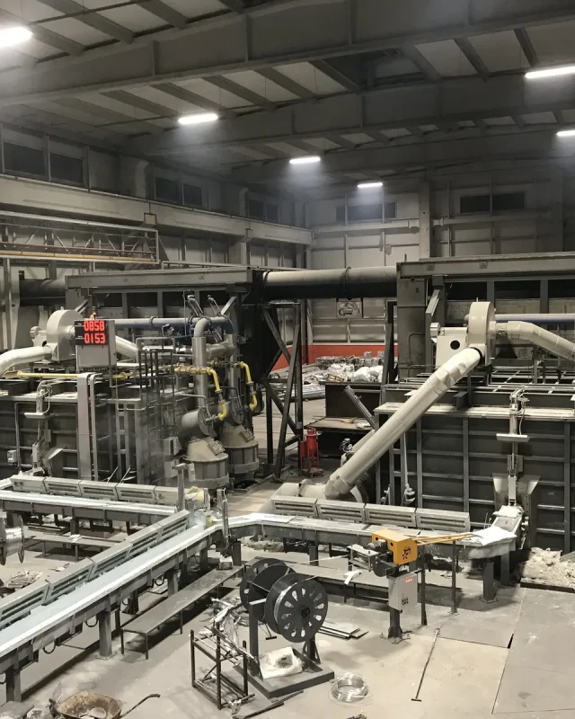
Melting and Holding Furnaces
Reverberatory-type body, single- or twin-chamber design, tilting metal transfer.
DISCOVER
Charging & Cleaning Systems
Automatic charging machine, bucket and platform; a cycle that shortens door-open time.
DISCOVER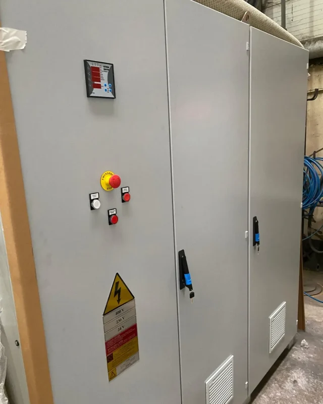
PLC & SCADA Systems
Combustion management, temperature control and reporting; furnace and line on the same screen.
DISCOVER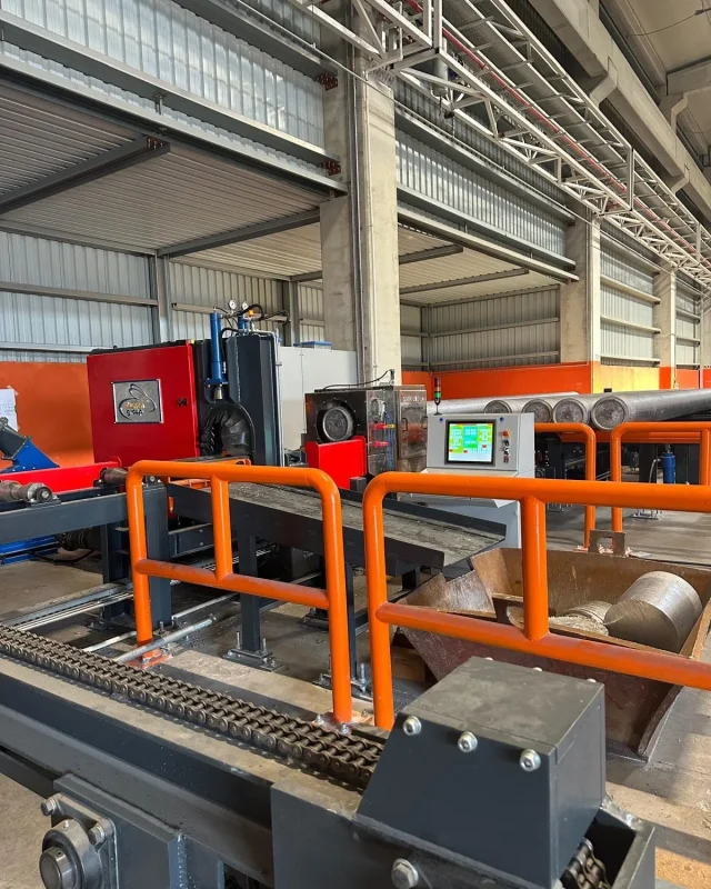
Service & Maintenance
First heat-up after refractory work, commissioning, scheduled maintenance and refurbishment.
DISCOVERLet’s design your melting line together
How many tonnes do you cast per shift, what is the scrap share in your charge, and how much space do you have on site? We design the furnace, charging machine and automation around these three answers.
Request a Quote