
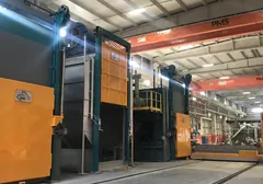

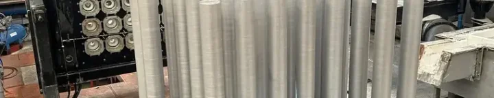
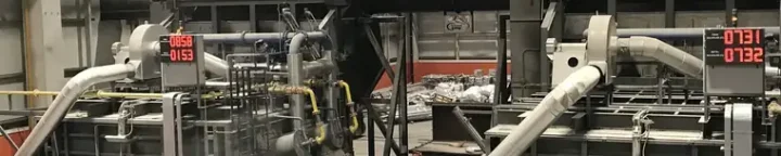

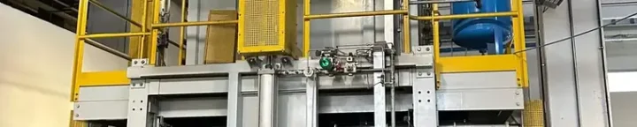
We safeguard metal quality between the furnace and the casting pit
We build the rotary degasser, the ceramic foam filter and the heated launder as a single line, not as separate pieces of equipment. Hydrogen and oxide in molten aluminium show up as porosity and cracks after solidification; we deal with a large share of these defects before the metal even gets to casting.
- Degassing method
- Rotary inline
- Purge gas
- N₂ or Ar
- Filter
- CFF 30 – 50 ppi
- Hydrogen target
- < 0.10 ml/100 g
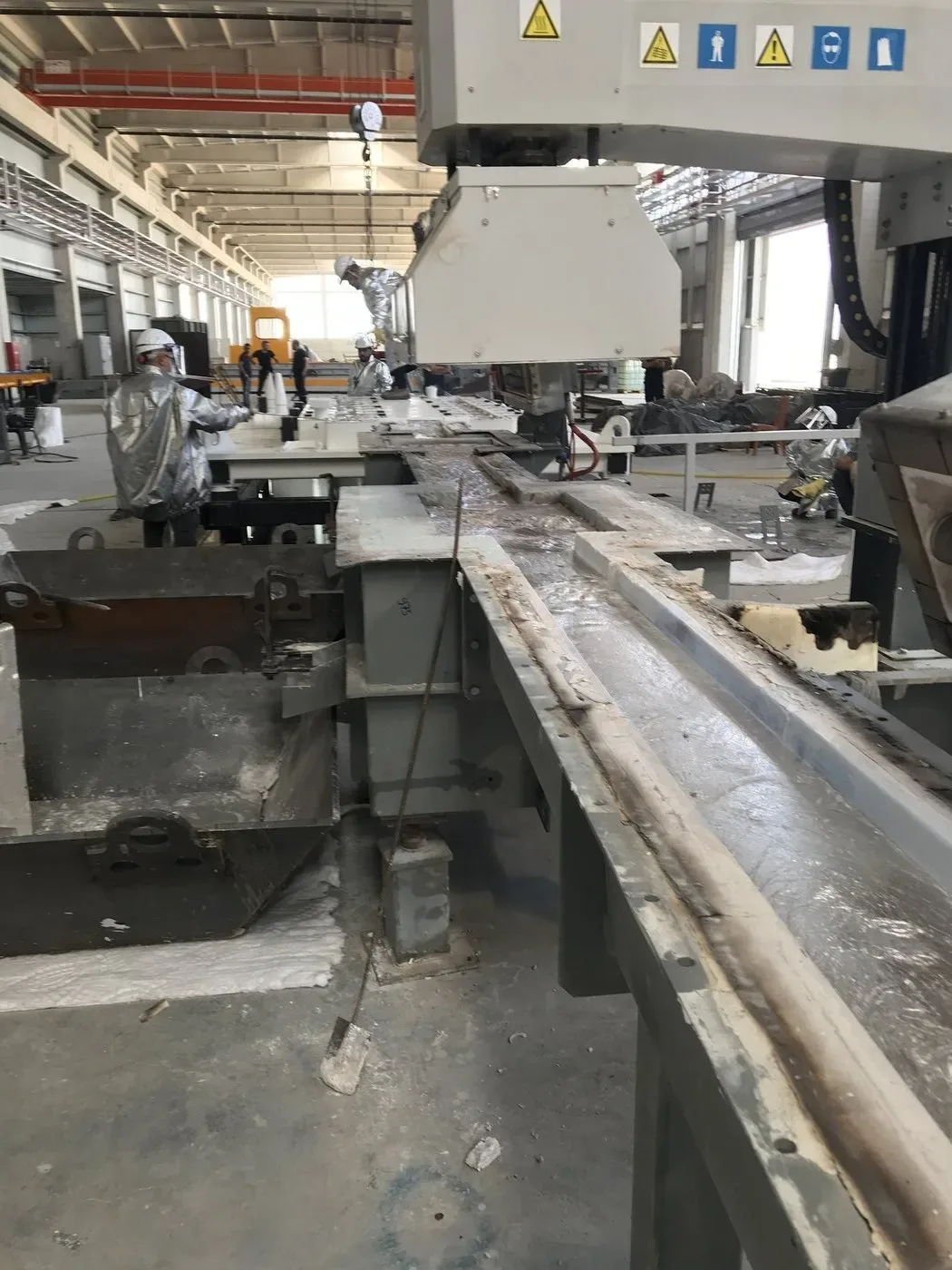
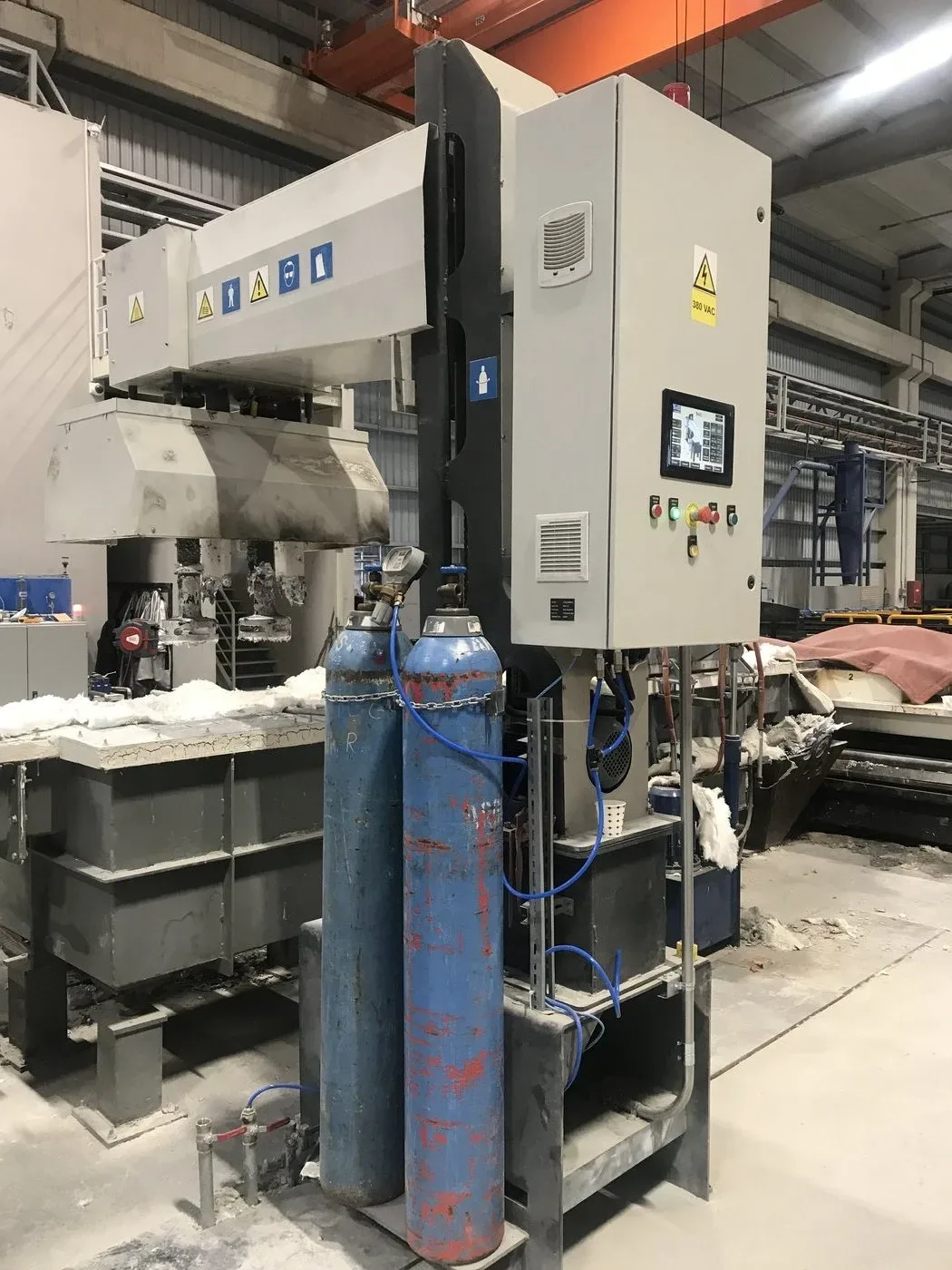
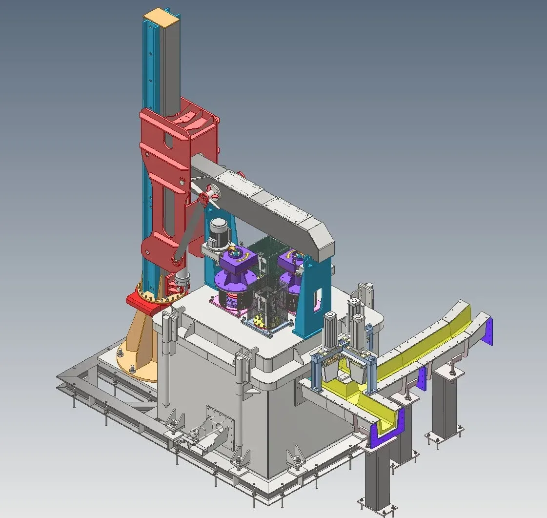
Why the Gumen Makina Degassing System?
Hydrogen removal
The rotor breaks nitrogen or argon into small bubbles inside the molten metal; as each bubble rises to the surface, it carries dissolved hydrogen with it. With the right rotor speed and gas flow rate, levels below 0.10 ml/100 g can be reached.
Ceramic foam filter
A CFF plate with 30–50 ppi porosity separates the oxide film and inclusions from the metal. The pore density is selected according to the alloy and the casting flow rate: a finer filter means cleaner metal, but also a higher pressure drop.
Full line integration
The degasser, filter box and launder run on the same PLC infrastructure. No separate control island is left between the melting furnace and the casting machine.
Easy maintenance
The filter plate and rotor are positioned so that they can be changed between shifts. The launder covers are also designed to be removable for refractory maintenance.
Three units between the furnace and the pit
Inline Degassing Units
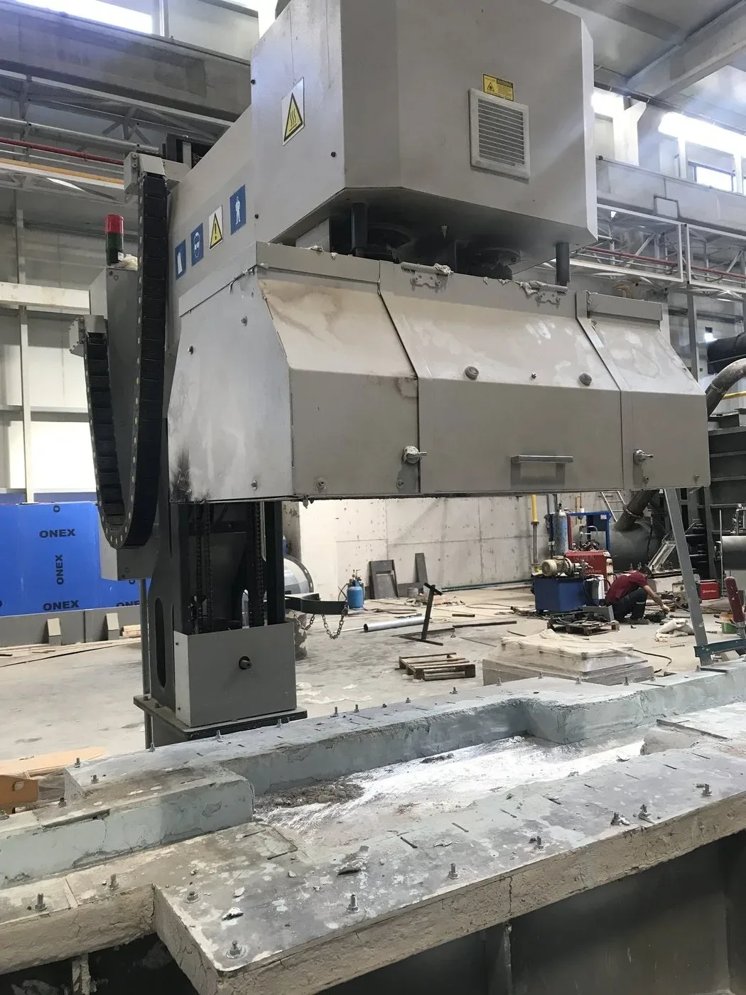
System structure: graphite rotor and shaft, gas distribution line, heated chamber, cover assembly and automation control. The metal is treated while it flows along the line, so no separate ladle operation is needed on the furnace side.
- Fine bubble distribution with a graphite rotor
- Operation with nitrogen or argon
- PLC-controlled gas flow rate and rotor speed
- Target hydrogen level < 0.10 ml/100 g
- Heated chamber to prevent temperature loss
- 1xxx – 7xxx series alloy compatibility
Ceramic Foam Filter (CFF) Units
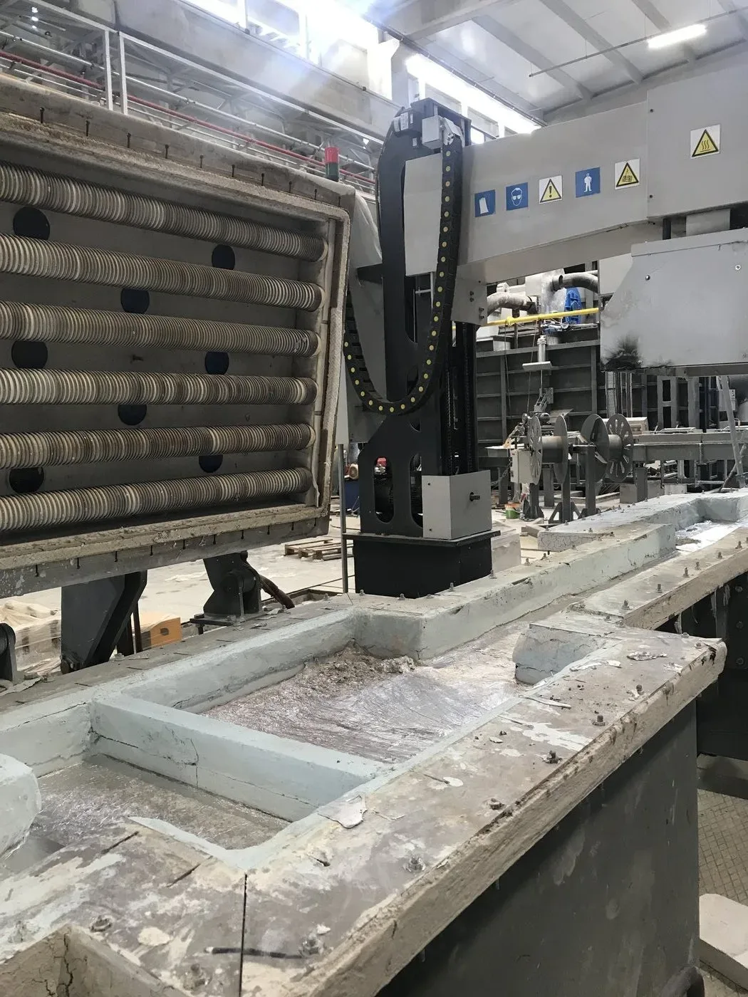
System structure: filter box, preheating system, CFF plate and gasket seat. It sits directly after the degasser: degassed metal does not go to the pit without passing through the filter.
- Plate options from 30 to 50 ppi
- Pore density selected by alloy and flow rate
- Capture of oxide film and inclusions
- Preheated filter box
- Plate changes between shifts
- Sizing by casting flow rate
Launder Line
System structure: refractory-lined channel, covers and heating elements, level measurement points and supporting structure. This is the path the metal takes from the furnace to the pit, and also the place where the temperature drops and the metal comes into contact with air.
- Heated or unheated line option
- Refractory-lined channel construction
- Heat and oxide control with a covered design
- Route design to suit the plant layout
- Level and temperature measurement points
- Single body with the degasser and filter
Technical documents and catalogues
We answer frequently asked questions
about metal quality
It is, but the defect is only postponed. Dissolved hydrogen cannot escape from the metal during solidification and remains as micro-porosity; this porosity comes back as blisters in extrusion and as cracks after heat treatment. If the share of your billets that are scrapped is high, this is where measuring should start.
Three items: gas type and flow rate (nitrogen is markedly cheaper than argon), filter replacement frequency and rotor service life. We build the line so that the gas choice can be changed later; we work out the cost calculation together with your alloy list and casting flow rate.
For extrusion billet, 30–40 ppi is usually enough; for thin sheet and foil it goes up to 50 ppi. As the pores get finer, cleanliness improves, but the pressure drop grows and the plate life gets shorter. We make the selection together with your alloy, casting flow rate and scrap ratio.
In most cases, yes. What decides it is the level difference and the distance between the furnace outlet and the casting pit: the metal has to flow along the slope of the launder itself. After measuring the site, we show the positions of the degasser and the filter box on the layout plan.
During commissioning, a sample is taken from the line and measured; the rotor speed and gas flow rate are adjusted according to this measurement. If you do not have a measuring instrument at your plant, we plan this step together with you in the commissioning programme.
We manufacture the equipment that makes up this solution in our own plant
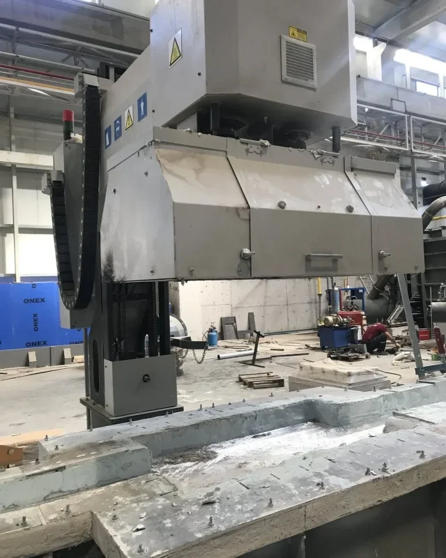
Degassing
Rotary inline degasser, ceramic foam filter box and heated launder line.
DISCOVER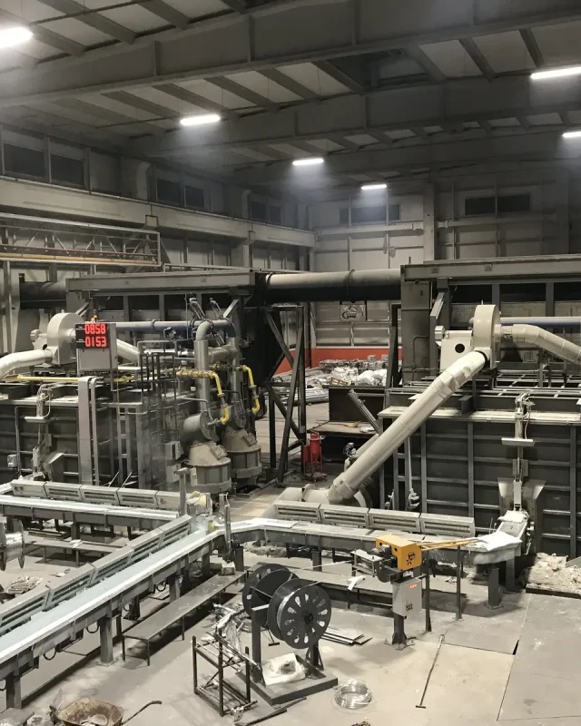
Melting and Holding Furnaces
Reverberatory-type body, single- or twin-chamber design, tilting metal transfer.
DISCOVER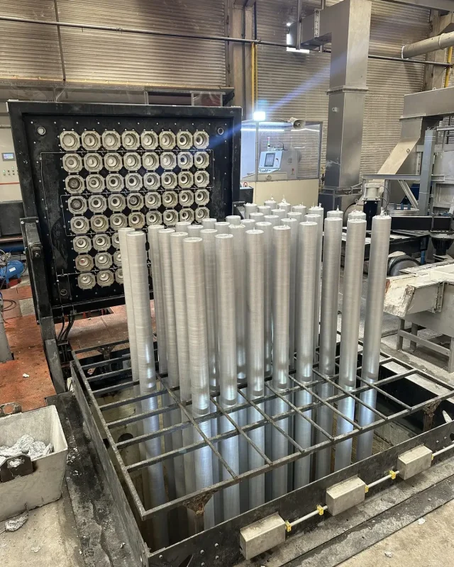
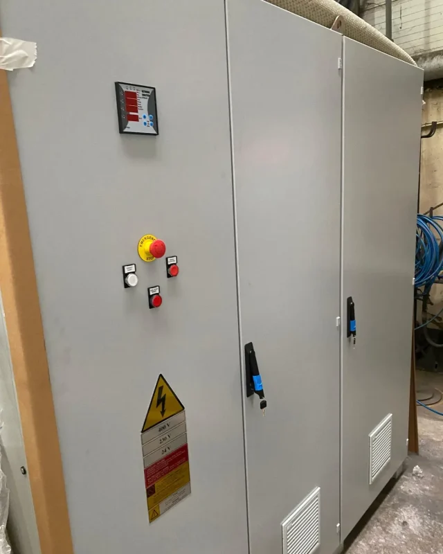
PLC & SCADA Systems
Gas flow rate, rotor speed and metal temperature are monitored on a single screen.
DISCOVERLet’s build your refining line together
Which alloys do you cast, what is the scrap ratio in your charge, and how much distance is there between the furnace outlet and the pit? The choice of degasser and filter largely follows from these three answers.
Request a Quote